製品名
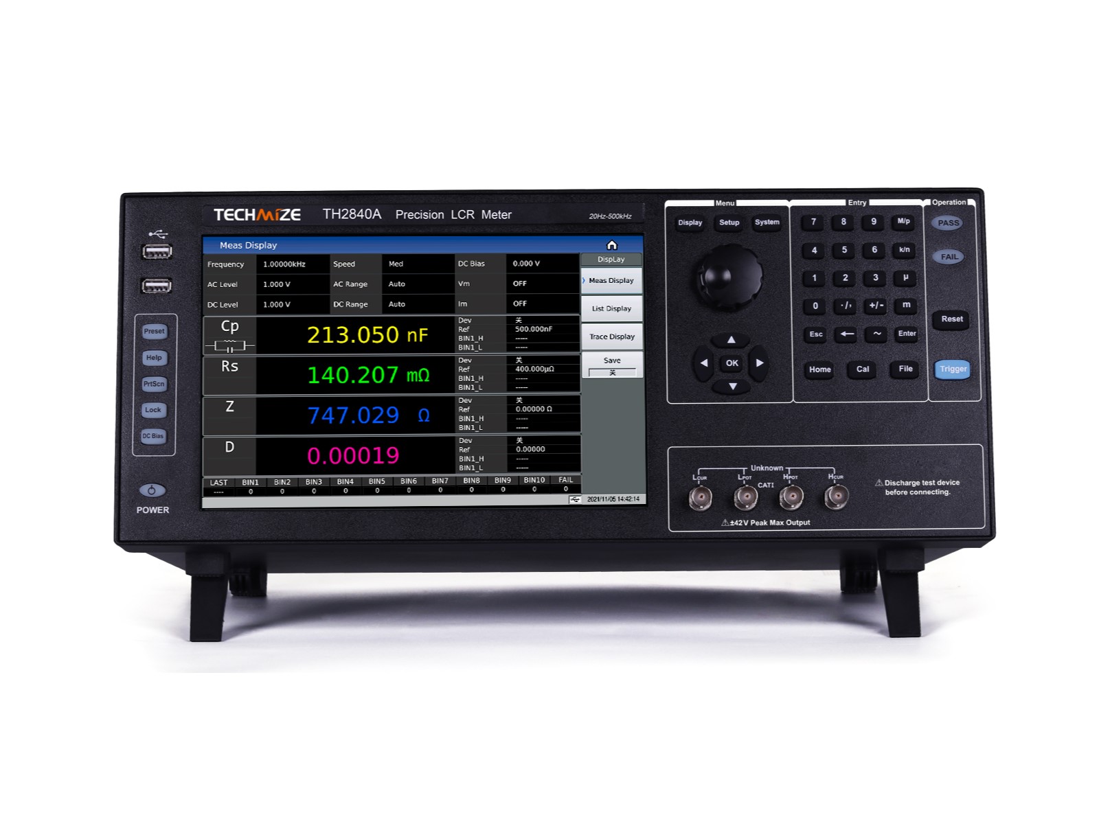
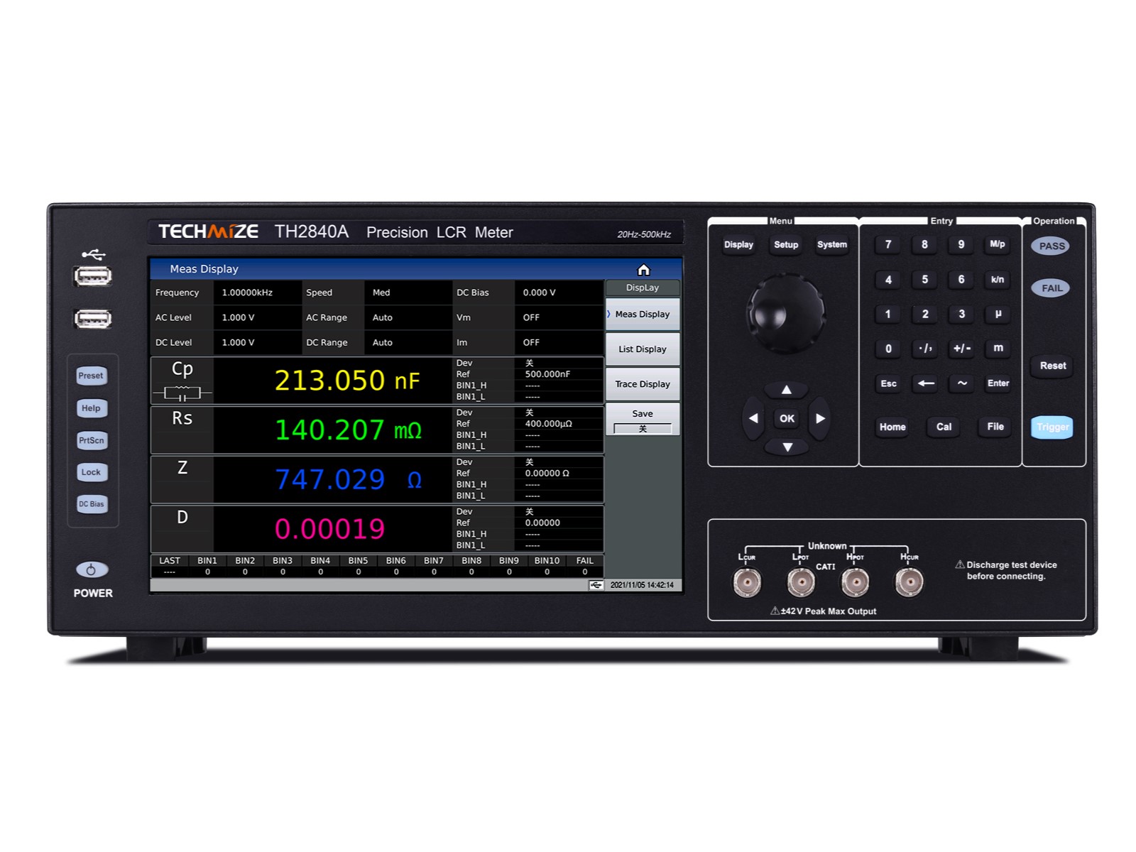
インピーダンスアナライザ TECHMIZE 型式:TH2840A【20Hz-500kHz】
価格
854,700円(税込)
型番
TH2840A
メーカー
概要
■製品仕様:
確度: 0.05%、 テスト周波数: 20Hz-500kHz、
テスト電圧: 5mV-20V、 DCバイアス: ±40V/100mA、
独立電流源: ±2A、 4パラメータ測定、 201点リスト・スイープ、
マルチ・パラメータ・グラフィック解析、
10.1インチ・タッチスクリーン、 DCR
特徴
■ テスト周波数:20Hz – 2MHz
■ 高い安定性と一貫性:14のレンジ構成
■ 高出力:
- 信号レベル:20VAC / 100mAAC
- 内蔵DCバイアス:±40VDC / 100mADC
- 内蔵電流源:±2A
■ DCRレベル:20VDC / 100mADC
■ 高速:デュアルCPUアーキテクチャ、測定速度は最大1000回/秒
■ 高解像度:10.1インチ、解像度1280×800、キャパシティブタッチスクリーン
■ 3つのテスト方法:ポイントテスト、リストスキャン、グラフスキャン
■ 4パラメータ測定
■ 201ポイントマルチパラメータリストスキャン機能
■ グラフィックスキャン機能:任意に4つの軌跡を選択可能、1/2/4分割画面をサポート
■ ソーティング機能:LCRモードで10レベルのソーティング
■ 高い互換性:SCPI/MODBUS命令セットをサポートし、KEYSIGHT E4980A、E4980AL、HP4284Aに対応
Specifications
| Model | TH2840A | TH2840B | ||
| Display | Display | 10.1″Touch Screen | ||
| Ratio | 16:09 | |||
| Resolution | 1280×RGB×800 | |||
| Parameter | Test Mode | Four Parameter Selectable | ||
| AC | Cp/Cs, Lp/Ls, Rp/Rs, |Z|, |Y|, R, X, G, B, θ, D, Q, VAC, IAC | |||
| DC | RDC, VDC, IDC | |||
| Frequency | Range | 20Hz-500kHz | 20Hz-2MHz | |
| Accuracy | 0.01% | |||
| Resolution | 0.1mHz (20.0000Hz-99.9999Hz) | |||
| 1mHz (100.000Hz-999.999Hz) | ||||
| 10mHz (1.00000kHz-9.99999kHz) | ||||
| 100mHz (10.0000kHz-99.9999kHz ) | ||||
| 1Hz (100.000kHz-999.999kHz) | ||||
| 10Hz (1.00000MHz-2.00000MHz) | ||||
| AC test signal mode | Rated value (ALC OFF) | Set the voltage as the Hcur voltage when the test terminal is open | ||
| Set the current to be the current flowing from Hcur when the test terminal is short-circuited | ||||
| Constant value (ALC ON) | Keep the voltage on the DUT the same as the set value | |||
| Keep the current on the DUT the same as the set value | ||||
| Test Level | AC Voltage | 5mVrms-20Vrms | F≤1MHz 5mVrms-20Vrms | |
| F>1MHz 5mVrms-15Vrms | ||||
| Accuracy | ±(10%×Set Value+2mV) (AC less than 2Vrms) | |||
| ±(10%×Set Value+5mV)(AC>2Vrms) | ||||
| Resolution | 1mVrms(5mVrms-0.2Vrms) | |||
| 1mVrms(0.2Vrms-0.5Vrms) | ||||
| 1mVrms(0.5Vrms-1Vrms) | ||||
| 10mVrms(1Vrms-2Vrms) | ||||
| 10mVrms(2Vrms-5Vrms) | ||||
| 10mVrms(5Vrms-10Vrms) | ||||
| 10mVrms(10Vrms-20Vrms) | ||||
| AC Current | 50μArms-100mArms | |||
| Resolution (100Ω Internal Resistance) | 10μArms (50μArms-2mArms) | |||
| 10μArms (2mArms-5mArms) | ||||
| 10μArms (5mArms-10mArms) | ||||
| 100μArms (10mArms-20mArms) | ||||
| 100μArms (20mArms-50mArms) | ||||
| 100μArms (50mArms-100mArms) | ||||
| RDC Test | Voltage | 100mV-20V | ||
| Resolution | 1mV(0V-1V) | |||
| 10mV(1V-20V) | ||||
| Current | 0mA-100mA | |||
| Resolution | 10μA(0mA-10mA) | |||
| 100μA(10mA-100mA) | ||||
| DC Bias | Voltage | 0V-±40V | ||
| Accuracy | AC=<2V 1%× Set Value+5mV | |||
| AC>2V 2%×Set Value+8mV | ||||
| Resolution | 1mV(0V-1V) | |||
| 10mV(±1V- ±40V) | ||||
| Current | 0mA-±100mA | |||
| Resolution | 10μA(0mA-10mA) | |||
| 100μA(10mA-100mA) | ||||
| Built-in current source | Current | 0mA-2A | ||
| Accuracy | I>5mA ±(2%×Set Value+2mA) | |||
| Resolution | 1mA | |||
| Test terminal configuration | Four Terminal Pair | |||
| Test cable length | 0m, 1m, 2m, 4m | |||
| Output impedance | 30Ω, ±4%@1kHz | |||
| 100Ω, ±2%@1kHz | ||||
| Computation | The absolute deviation from the nominal value Δ, the percentage deviation from the nominal value Δ% | |||
| Equivalent way | Series, Parallel | |||
| Calibration function | OPEN, SHORT, LOAD | |||
| Measurement average | 1-255 | |||
| Range selection | AUTO, HOLD | |||
| Range configuration | LCR | 100mΩ, 1Ω, 10Ω, 20Ω, 50Ω, 100Ω, 200Ω, 500Ω, 1kΩ, 2kΩ, 5kΩ, 10kΩ, 20kΩ, 50kΩ, 100kΩ | ||
| Rdc | 1Ω, 10Ω, 20Ω, 50Ω, 100Ω, 200Ω, 500Ω, 1kΩ, 2kΩ, 5kΩ, 10kΩ, 20kΩ, 50kΩ, 100kΩ | |||
| Measuring time (ms) | Fast+: 1ms | |||
| Fast:3.3ms | ||||
| Middle: 90ms | ||||
| Slow: 220ms | ||||
| Highest accuracy | 0.05% (refer to the instruction manual for details) | |||
| Measurement display range | ||||
| Cs, Cp | 0.00001pF-9.99999F | |||
| Ls, Lp | 0.00001μH-99.9999kH | |||
| D | 0.00001-9.99999 | |||
| Q | 0.00001-99999.9 | |||
| R, Rs, Rp, X, Z, RDC | 0.001mΩ-99.9999MΩ | |||
| G, B, Y | 0.00001μs-99.9999S | |||
| VDC | ±0V-±999.999V | |||
| IDC | ±0A-±999.999A | |||
| θr | -3.14159-3.14159 | |||
| θd | -179.999°-179.999° | |||
| Δ% | ±(0.000%-999.9%) | |||
| Multi-function parameter list scan | Dots Number | 201 points, average times can be set for each point, and each point can be sorted separately | ||
| Parameter | Test frequency, AC voltage, AC current, DC BIAS voltage, DC BIAS current (100mA), DC BIAS current (2A) | |||
| Trigger mode | Sequence SEQ: After a trigger, measure at all sweep points, and /EOM/INDEX will output only once | |||
| Step STEP: Perform a sweep point measurement each time it is triggered, and each point outputs /EOM/INDEX, but the list sweep comparator result is only output at the last /EOM |
||||
| Other features | 1. Scan parameters and test parameters have multiple copy functions | |||
| 2. Delay can be set for each scan point | ||||
| Comparators | Each sweep point can measure up to four test parameters, each parameter can set upper and lower limits, all test parameters are qualified, output PASS signal, otherwise output FAIL signal, no upper and lower limits are set, no judgment | |||
| Graphic scan | Scan points | 51, 101, 201, 401, 801 Optional | ||
| The results | The extreme value of each parameter and the sweep parameter value at the point where the cursor is located and the corresponding test parameter value | |||
| Scan trajectory | 1-4 test parameters can be selected arbitrarily, the scanning curve can be divided into one screen, two screens, or four screens. | |||
| Display range | Real-time automatic, locked | |||
| Coordinate ruler | Logarithmic, linear | |||
| Scan parameters | Frequency, AC voltage, AC current, DCV BIAS / DCI BIAS (100mA) / DCI BIAS (2A) | |||
| Trigger mode | single | Manually trigger once, and complete a scan from the start point to the end point, and the next trigger signal starts a new scan | ||
| continuous | Infinite loop scanning from start to end | |||
| Results save | Graphics, files | |||
| Comparators | Bin | 10Bin, PASS, FAIL | ||
| Bin deviation setting | Deviation value, percentage deviation value, off | |||
| Bin mode | Tolerance, continuous | |||
| Bin count | 0-99999 | |||
| Discrimination | Up to four parameter limit ranges can be set for each file. The corresponding file number is displayed within the setting range of the four test parameter results. If the maximum file number range is exceeded, FAIL is displayed. The test parameters without the upper and lower limits are automatically ignored. | |||
| PASS/FAIL indication | Meet Bin1-10, the PASS light on the front panel is on, otherwise the FAIL light is on | |||
| Data cache | 201 measurement results can be read in batches | |||
| Store call | Inside | About 100M non-volatile memory test setting file | ||
| External USB | Test setting file, screenshot graph, record file | |||
| Keyboard lock | The front panel keys can be locked, other functions to be expanded | |||
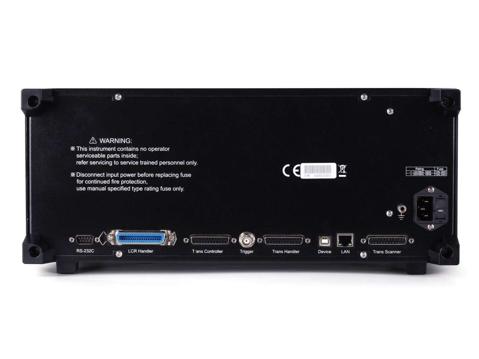
| Interface | USB HOST | 2 USB HOST ports, can connect mouse and keyboard at the same time, only one U disk can be used at the same time | ||
| USB DEVICE | Universal serial bus socket, small type B (4 contact positions); compatible with USB TMCUSB488 and USB2.0, the female connector is used to connect an external controller. | |||
| LAN | 10/100M Ethernet adaptive | |||
| HANDLER | Used for Bin signal output | |||
| External DC BIAS control | Support TH1778A | |||
| RS232C | Standard 9-pin, cross | |||
| RS485 | Can accept modification or external RS232 to RS485 module | |||
| Power-on warm-up time | 60 Minutes | |||
| Input voltage | 100-120VAC/198-242VAC Option, 47-63Hz | |||
| Power consumption | More than 130VA | |||
| Size (WxHxD) mm3 | 430x177x265 | |||
| Weight (kg) | 11kg | |||
Accessary
| Standard | ||||||
| Accessories name | Model | |||||
| Fixture | TH26048 | 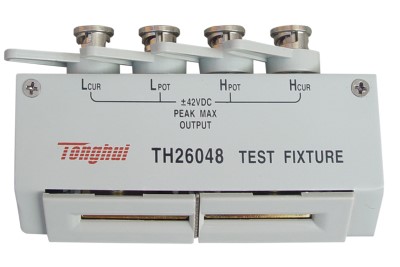 |
||||
| Short circuit | TH26010 | 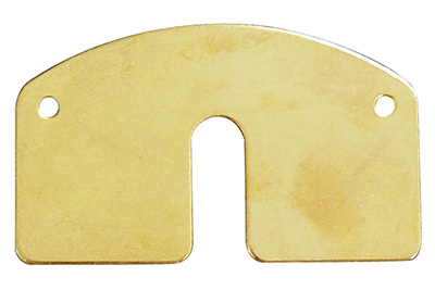 |
||||
| Kelvin test lead with box four-terminal insulation and lock | TH26011BS | 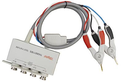 |
||||

